Your Measurements Are Wrong (and It's Probably Not Your Tektronix Equipment)
Posted on 2026-08-21 by Marcus Feld
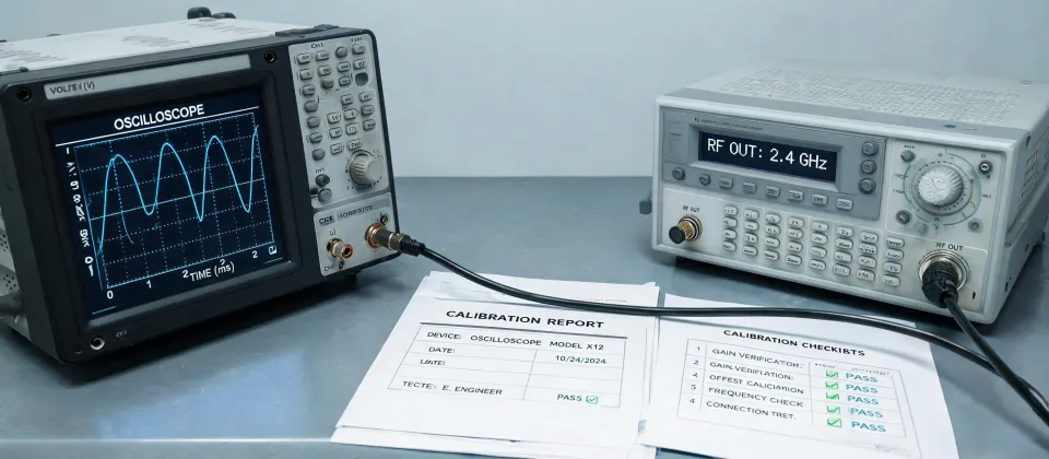
I'm the person who reviews test reports before they leave our plant. Verification documents, calibration records, production line sign-offs—roughly 200+ unique deliverables every year. In our Q1 2025 quality audit, I rejected 18% of first submissions.
Not because the numbers were obviously wrong. Because the measurement methods were.
This isn't a story about lazy engineers. It's about good engineers using capable equipment—Tektronix oscilloscopes, Fluke meters, modern analyzers—in ways that quietly exceeded the tools' boundaries. Nobody caught it until the report landed on my desk.
The Problem You Think You Have: A Bad Instrument
When engineers come to me with measurement complaints, the pattern rarely varies. "Our readings are inconsistent." "The analyzer is drifting." "I need to submit a capital request." They're convinced the gear is the weak link.
Sometimes they're right. Maybe one time in five. The other four, the instrument was fully capable of the measurement. The problem was the assumptions baked into the test setup. Nobody asked whether the tool matched the physical quantity being measured. Nobody asked whether the measurement principle fit the signal.
The Deep Cause: Every Instrument Has a Boundary
What most people don't realize is that a spec sheet describes what an instrument does under defined conditions. Not your conditions. That's written in the manual and in the application notes—but the manual rarely gets read past the quick-start guide.
I see three patterns over and over in the reports I reject.
Pattern 1: The wrong tool for the measurement
Insulation resistance is the clearest example. If you need to verify insulation integrity on a motor winding, a standard multimeter—even a classic like the Fluke 87 true RMS multimeter—applies only a couple of volts across its leads. Insulation resistance testing needs test voltage—usually 500V or 1000V, sometimes more—to expose leakage paths that only conduct under high voltage.
At 9V, damaged insulation looks perfectly fine. Your multimeter reads "infinite" resistance. You sign off on a motor with a fault that could arc-flash in service. That's why "how to use a megger insulation tester" is one of our most-searched terms. Not because clipping leads into a terminal is hard. Because knowing when you need an insulation tester instead of a multimeter is a boundary question. And boundary questions are exactly where errors live. The megger applies the right test voltage—per IEC 61557 requirements—so it exposes what the multimeter can't see.
Pattern 2: The measurement principle doesn't match the signal
The true RMS versus average-responding question is the classic version of this. An average-responding meter assumes a clean sine wave and applies a correction factor. A true RMS meter—like the 87 series—computes the actual heating value of the signal, harmonics and all.
Feed a PWM drive output into an average-responding meter, and you'll get a number that looks entirely plausible and is off by 20% to 40%. No warning. No error message. Just a confident, attractive display of wrongness.
During audits, we check measurement principle against signal type. If someone measured a VFD output with an average-responding meter, I catch it and send the report back. But the engineer who made that mistake was never told they'd made a mistake. They filed the original report believing the method was fine. That's the danger: boundary errors don't announce themselves as errors.
Pattern 3: Complex instruments treated as black boxes
Here's something vendors won't tell you: every complex instrument has boundaries you can't see from the front panel. Take a Tektronix spectrum analyzer USB model—the RSA series. Genuinely capable instruments; I've verified plenty of RF measurements with them, honestly. But they have input limits, reference level requirements, and resolution bandwidth behaviors that directly affect what the trace shows you. Leave everything on defaults, feed it a signal outside its comfort zone, and it will generate a clean, beautiful, wrong answer.
We had a Q1 2024 incident with PROFINET encoders—3,000 units for a production line. Signal integrity verification was wildly inconsistent. The production engineer pushed to replace the analyzer; every spreadsheet analysis supported it. Something felt off. I ran a blind test—same encoder, same analyzer, two different setups. Results diverged sharply. Root cause: grounding configuration and probe connection point. The fixture was picking up common-mode noise that swamped the PROFINET signal levels. The analyzer was fine. An $18,000 replacement would have changed nothing.
What Bad Measurements Actually Cost
It's easy to treat measurement errors as abstract. They aren't.
In 2023, a batch passed our internal verification. Calibrated equipment. Signed reports. No obvious gaps. The customer ran their incoming inspection with a megger insulation tester at the specified test voltage and rejected the entire shipment.
That cost us a $22,000 redo and pushed the launch back six weeks. The root cause? Our internal test used a multimeter's low-voltage resistance range. It looks like an insulation test on paper. It isn't one. Re-testing with the proper tool found that 8% of that batch had insulation weakness that should never have left the building.
If that customer hadn't insisted on proper incoming inspection, those units would have gone into service. The weaknesses would have surfaced later—unpredictably, potentially with a technician's hands in the same cabinet. Electrical faults in industrial equipment aren't just production disruptions; they're life-safety events. I try not to think about that part.
PROFINET encoder failures carry a different but equally real price. Signal integrity failures mean dropped data. Dropped data on an automation network means machine stops—or worse, unpredictable machine behavior. An encoder that reports position erratically can direct a robot arm somewhere it shouldn't go. You don't get a second chance to replay that scenario.
There's also the hidden overhead that never shows up on a P&L line. Every rejected report consumes someone's time to investigate and redo. Plus, borderline submissions trigger verification rounds, follow-up conversations, documentation corrections. The $22,000 redo didn't include the two days our quality team spent tracing which other reports might be affected by the same flawed method.
Bottom line: measurements are the foundation of every decision downstream. When the foundation is off by 30%, everything built on it is suspect.
What We Actually Changed
Four years and 800+ reports later, I've stopped framing this as an equipment problem. It's basically a boundaries problem.
We implemented a three-question verification checklist. It's embarrassingly simple:
- What physical quantity am I actually measuring? Resistance, insulation integrity, and continuity are different things even though the test terminals look identical. Define the quantity before you touch a probe.
- Does my instrument's measurement principle fit the signal? True RMS for non-sinusoidal waveforms. A proper insulation tester for dielectric integrity. A deliberately configured spectrum analyzer for RF.
- Is my setup inside the instrument's documented boundaries? Check specifications on the manufacturer's official website. For Tektronix equipment, that's tektronix.com—not a reseller's listing—and verify probe connections, grounding, and input levels.
One more principle has saved us more times than I can count: if a specialist tool exists for a specialist measurement, use it. A megger insulation tester for insulation resistance, with the test voltage set to the standard you're working under. A true RMS handheld for drive outputs. A spectrum analyzer with input attenuation, reference level, and RBW dialed in deliberately.
That's the thing about professional boundaries. I'd rather work with an instrument that knows its limits than one that claims to do everything. I'd rather trust a vendor who says "this isn't our strength—here's who does it better" than a supplier who promises a universal solution. Instruments are no different. (Note to self: we should get this into the training manual. Long overdue.)
Boundaries are honest. Instruments that respect them—and engineers who respect them—are the ones whose reports pass on the first submission. Our rejection rate dropped from 18% to 6% in the first year after we started asking these three questions.
My experience is based on roughly 200 reviewed reports per year in production and industrial maintenance contexts. If you're in a stable lab environment with fully documented setups, you may see fewer of these patterns. But before you replace your next instrument, ask the three questions. You might save yourself $18,000.

Marcus Feld
Marcus Feld is an electrical test and measurement analyst specializing in multimeters, oscilloscopes, clamp meters, insulation testers, spectrum analyzers, and data loggers. He applies IEC 61010-2-030 and IEC 61010-031 concepts while examining measurement category, bandwidth, true-RMS response, input loading, and stated uncertainty. His work helps maintenance engineers and test teams choose safe instruments with performance suited to the signals and environments they actually measure.
Leave a technical comment