Tektronix TBS1000C Troubleshooting Checklist: 6 Steps Before You Trust the Signal
Posted on 2026-09-16 by Marcus Feld
-
Step 1: Sketch the Signal Path Before You Probe Anything
-
Step 2: How to Test a Rice Lake Load Cell as a Passive Bridge
-
Step 3: Use a Multimeter With Amp Clamp for Current Checks
-
Step 4: Set Up the Tektronix TBS1000C Series Digital Oscilloscope Before You Trust It
-
Step 5: Use Tektronix Arbitrary Function Generators To Make the Test Repeatable
-
Step 6: When Faults Are Intermittent, Bring in a Real Time Spectrum Analyzer
-
Final Notes: What Makes This Checklist Fail
I've spent 14 years helping engineers choose and troubleshoot test equipment. In that time, I've personally made and documented 12 significant measurement-setup mistakes that added up to roughly $16,000 in wasted rework and delays. The pattern was never a broken instrument. It was a broken assumption. I assumed the probe was compensated. I assumed the range was right. I assumed the sensor was the problem because the sensor was the only part I looked at.
This checklist is the routine I use now when a reading looks wrong, when a new transducer arrives, or when a system worked yesterday and refuses to cooperate today. It takes about 20 minutes. Use it before you re-calibrate something, before you open a warranty case, and before you tell anyone that the new oscilloscope is faulty.
Step 1: Sketch the Signal Path Before You Probe Anything
Start by drawing a simple diagram of the signal path. People skip this because they want to solve a problem fast. But if you don't know the expected signal at each point, you can't interpret the measurement once you have it.
A Rice Lake load cell example: load cell, cable, junction box, weight indicator, PLC analog input. If the scale says 2,000 lb when a 500 lb test weight is sitting on it, what should you check first? That depends on whether the indicator itself shows 500 lb before the PLC. If it does, the problem is downstream. If it doesn't, you haven't narrowed it down yet.
I wasted a full afternoon in 2018 watching a noisy signal on a scope because I never asked what the clean signal should look like. A napkin diagram with expected levels would have pointed me to the power supply in five minutes.
Step 2: How to Test a Rice Lake Load Cell as a Passive Bridge
If someone asks how to test a Rice Lake load cell, the honest answer starts with a digital multimeter, not an oscilloscope. A load cell is a strain gauge bridge. The fast checks are resistance checks. They catch open bridges, shorted cables, and obvious damage before you power anything.
Disconnect the load cell from the junction box or indicator first. Then measure input resistance across the excitation wires and output resistance across the signal wires. Compare those readings with the manufacturer's datasheet for that exact model.
I am not giving a universal resistance value because that led to my own costly mistake. In my first year, I rejected a 1000-ohm load cell because I expected 350 ohms. The nameplate said 1000 ohms. The cell was fine. The $600 replacement was unnecessary. The lesson wasn't about load cells; it was about checking assumptions against the written spec.
The point of this step isn't to prove the load cell is good. It's to get a repeatable baseline.
If the reading jumps when you move the cable, inspect the strain relief and connector. Moisture in a junction box can also create unstable readings that only show up after the system warms up. High-voltage insulation tests are not a default tool here; use only what the load cell manufacturer approves.
Step 3: Use a Multimeter With Amp Clamp for Current Checks
When the signal leaves the load cell as a 4-20 mA loop, you need to know if current is flowing without opening the loop. A multimeter with amp clamp is convenient because you clamp around one wire and read current. But check the clamp meter's resolution first. Many general-purpose clamp meters can only resolve 10 mA steps. That is useless for a 4-20 mA signal.
If you don't have a low-current mA clamp, don't conclude the loop is open just because the display looks wrong. It may simply be quantizing the reading too coarsely. I once chased a transmitter problem that was actually a tool-selection problem: the clamp meter wasn't designed for loop current, and every reading looked slightly off.
When you do use a multimeter with amp clamp, clamp around one conductor, not around a cable containing both wires. The magnetic fields cancel, and you'll get a reading near zero even when current is flowing.
Step 4: Set Up the Tektronix TBS1000C Series Digital Oscilloscope Before You Trust It
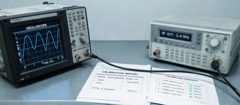
This is the step people skip most. The Tektronix TBS1000C Series Digital Oscilloscope is reliable, but it will display whatever your probe delivers. If the probe is not compensated, the displayed amplitude and waveshape will be wrong.
For a passive 10x probe, set the probe switch to 10x and make sure the channel menu matches. Most newer scopes auto-detect, but not always. Then connect the probe tip to the front-panel Probe Comp connector, connect the ground lead to the ground clip, and press Autoset. The square wave should have a flat top and sharp corners. If the corners are rounded, adjust the compensation trimmer until they are square.
A 1x/10x mismatch is a classic. In 2022, a customer sent back an oscilloscope because amplitudes were ten times too low. The scope was fine. The probe switch was in 1x while the scope was set to 10x. That check takes three seconds.
After compensation, set the vertical scale so the signal occupies at least a few divisions. Like most beginners, I once told everyone a sensor had no output because I was looking at a 30 mV signal on a 5 V/div setting. The waveform was there; I couldn't see it because of my scale. Zoom in to the expected amplitude and adjust the offset if needed.
Step 5: Use Tektronix Arbitrary Function Generators To Make the Test Repeatable
Tektronix arbitrary function generators are underused outside design labs. An arbitrary function generator is not just for sine waves; it's for replacing an unknown signal with a repeatable one.
If you suspect a PLC analog input scaling issue, disconnect the sensor and feed a known voltage or step signal into the input. If the display follows the expected change, the input side is fine and the sensor or wiring is the problem. If the display doesn't follow, you've narrowed it to the front end or configuration.
Don't try to drive a raw load cell directly with a function generator. A load cell needs bridge excitation and a mV/V relationship, so use the correct simulator for that part. Use the AFG on the next block in the chain, where the signal is at a compatible level. The goal is to isolate the problem, not to calibrate the scale.
When I compared a manual hand-loading test with the same signal injected from an AFG, the contrast finally made sense. Manual tests were never exactly the same twice. The AFG gave the same 2 V, 5 V, and 10 V steps every time. Repeatability matters more than excitement.
Step 6: When Faults Are Intermittent, Bring in a Real Time Spectrum Analyzer
If everything above passes and the problem still appears when a motor drive, pump, or radio transmitter turns on, start thinking about interference. A normal oscilloscope might show random noise, but it doesn't always tell you which frequency is causing the trouble.
A real time spectrum analyzer is better for catching short frequency bursts that come and go. It is not the first tool to grab. It is the final tool after you've eliminated the simple issues. If you see a burst repeat every time the VFD starts, you have a direction to go. If you don't, you're still guessing.
Final Notes: What Makes This Checklist Fail
The six checks fail when you don't record what you found. Write each reading down. Save a screenshot from the TBS1000C. Note which probe, which input, and which settings you used. Memory is terrible at comparing waveforms from last Thursday.
- Change one variable at a time. If you replace a probe and change the input range in the same step, you won't know what fixed it.
- Record the baseline before you take anything apart. That alone has caught more problems than any high-end feature I've used.
- Follow the manufacturer manual for exact values. This article is a general diagnostic order, not a replacement for factory documentation.
After 14 years of helping people debug signals, I've come to believe that the instrument is rarely the liar. The setup, the missing datasheet, and the assumption are usually the culprits. A checklist won't make you smarter, but it stops the equipment from paying for your bad day.

Marcus Feld
Marcus Feld is an electrical test and measurement analyst specializing in multimeters, oscilloscopes, clamp meters, insulation testers, spectrum analyzers, and data loggers. He applies IEC 61010-2-030 and IEC 61010-031 concepts while examining measurement category, bandwidth, true-RMS response, input loading, and stated uncertainty. His work helps maintenance engineers and test teams choose safe instruments with performance suited to the signals and environments they actually measure.
Leave a technical comment