I Spent $3,200 on Probes Before Learning This Lesson (And It Still Hurts)
Posted on 2026-07-10 by Marcus Feld
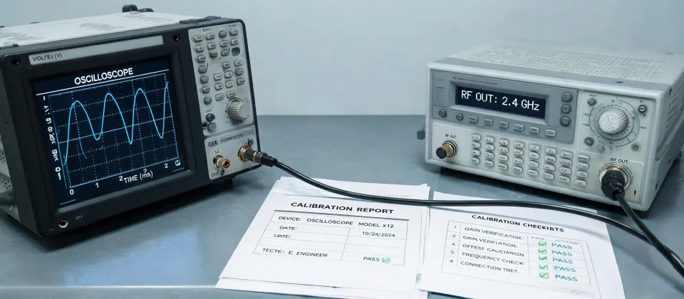
It was a Tuesday afternoon in late September 2022. I had just received a rush order from a customer who needed a quick measurement on a turbine flow meter signal. The deadline was tight, the troubleshooting was straightforward, and I felt confident. I grabbed a standard passive probe from the drawer, connected it to the Tektronix 453 oscilloscope sitting on the bench, and made the measurement.
The result looked fine. A clean, steady waveform. I sent the report and moved on.
Three days later, the customer called back. The signal was wrong. The entire batch of flow meters—over 40 units—had been assembled based on my reading. The actual pulse width was 15% shorter than what my oscilloscope showed. That error cost roughly $3,200 in rework, plus a 1-week delay on the project. And it was entirely my fault. Not the scope's, not the probe's. Mine.
That's when I started keeping a checklist. And that's why I'm writing this.
The Surface Problem: Why a Standard Probe Failed Me
Let's start with what I thought the problem was at the time. I assumed the Tektronix 453 was either out of calibration or that the probe had some internal defect. I checked the calibration certificate. It was valid. I swapped cables. Same reading. I tried a different channel. Same thing.
I eventually grabbed a different type of passive probe from another part of the lab—a Tektronix passive oscilloscope probe with a higher input capacitance rating—and the waveform changed. Suddenly, the pulse width matched what the customer expected. I felt stupid. Then I felt angry. Why didn't anyone tell me this mattered?
"When I compared the two probes side by side—same oscilloscope, same signal, same settings—I finally understood why probe selection isn't just a detail. It's the measurement itself."
Here's the thing: most people I talk to think the problem is about probe bandwidth. They think you just need a probe rated for the same frequency as your signal. And for DC or low-frequency measurements, that's kinda true. But for high-impedance sources—like the capacitive sensor inside a turbine flow meter—the probe's input capacitance can completely change what you're measuring.
The Deep Reason: Input Capacitance Changes Everything
Here's what I didn't understand until that $3,200 mistake. A passive oscilloscope probe doesn't just pick up a signal. It becomes part of the circuit. The probe's input capacitance (typically 8-15 pF for standard 10x probes) loads the source. If your source impedance is low—like a 50 ohm output—that extra capacitance doesn't matter. But if your source impedance is high—like a flow meter with a high-impedance capacitive sensor—the probe's capacitance acts as a low-pass filter, rounding off edges, reducing amplitude, and shifting timing.
Look at it this way:
- Standard passive probe (10x): Input capacitance around 10-15 pF. Great for signals under 100 MHz with low-impedance sources.
- Low-capacitance passive probe: Input capacitance around 3-8 pF. Better for high-impedance sources where signal fidelity matters.
- Active probe: Input capacitance under 1 pF. Expensive, but necessary for high-frequency or ultra-high-impedance measurements.
I only believed this after ignoring it. They warned me in training—'always consider probe loading.' I didn't listen. That was the reverse validation: I had to waste thousands to feel the truth.
The Cost of Getting It Wrong (It's More Than Money)
The obvious cost was the $3,200 in rework. But that was just the surface. The real cost was harder to measure:
- Credibility: That customer now double-checks every reading I send them. Trust that took years to build, damaged in one bad waveform.
- Time: We spent an entire week re-testing every flow meter. Meanwhile, other projects sat waiting.
- Morale: I felt like an amateur. And I wasn't. I'd been doing this for seven years at that point.
But here's the thing: I've seen this pattern so many times since then. Engineers—smart ones, experienced ones—grabbing whatever probe is closest. They assume that if the oscilloscope is good, the probe doesn't matter. They assume that if the waveform looks clean, it must be accurate.
And they're wrong.
My experience is based on about 50-60 troubleshooting cases involving high-impedance sensors. If you're working with RF or low-impedance outputs, your experience might differ significantly. I can't speak to how this applies to power electronics or high-frequency design. But for medium-speed, high-impedance industrial sensors? This pattern is consistent.
The Simple Fix: A Checklist (And a Moment of Self-Doubt)
So what do I do now? I maintain a checklist. It's not complicated. It's just three questions I ask myself before every measurement:
- What is the source impedance? If I don't know, I measure it or look up the datasheet.
- Is the probe's input capacitance appropriate for this source? If it's a high-impedance source, I use a low-capacitance probe or an active probe.
- What happens if I'm wrong? If the cost of error is high, I verify with a second measurement method—like using a known-low source or a different probe type.
That's it. Three questions. It takes 30 seconds. And it's saved me from at least a dozen similar mistakes since October 2022.
I recommend this approach if you're working with oscilloscopes—especially older models like the Tektronix 453, which doesn't have built-in probe compensation detection. But if you're using a modern scope with automatic probe detection and compensation, you might not need this level of caution for routine measurements. Then again, knowing the limitations of your equipment never hurts.
Bottom line: there's no universal 'best probe.' There's only the probe that fits your specific measurement. The moment I stopped blaming the equipment and started understanding the interaction between the probe and the source, my accuracy improved more than any calibration could offer.
I really should have learned this lesson from a book. Instead, I learned it from a $3,200 mistake.
Marcus Feld
Marcus Feld is an electrical test and measurement analyst specializing in multimeters, oscilloscopes, clamp meters, insulation testers, spectrum analyzers, and data loggers. He applies IEC 61010-2-030 and IEC 61010-031 concepts while examining measurement category, bandwidth, true-RMS response, input loading, and stated uncertainty. His work helps maintenance engineers and test teams choose safe instruments with performance suited to the signals and environments they actually measure.
Leave a technical comment